Qué buscas?
A stamped metal heat shield begins as sheet material, but the finished part is defined by much more than alloy grade and thickness. Embossing, formed ribs, flanges, edge returns, mounting features and local flat areas all influence whether a thin shield keeps its shape, fits the exhaust assembly and can be produced repeatedly.
For an OEM buyer, these details should be treated as engineering requirements rather than cosmetic features. A drawing that specifies only “stainless steel heat shield” or “embossed aluminum shield” still leaves major questions unresolved: Which areas are embossed? Which surfaces must remain flat? Where is the part located during inspection? How are the edges finished? Which formed features are critical to fit?
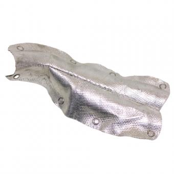
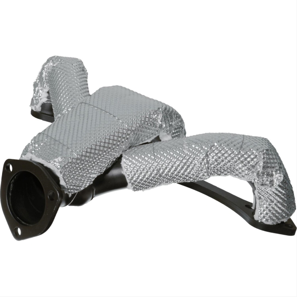
BSTFLEX supplies metal stamping heat shields and supports custom exhaust shielding from drawings, samples and application requirements. Existing rigid product references include the Exhaust Manifold Heat Shield and Stamped Turbocharger Heat Shield.
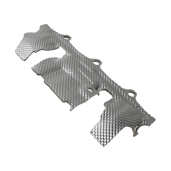
A stamped metal heat shield is a formed sheet-metal component designed to create a thermal barrier between a hot component and surrounding parts. Automotive and exhaust applications commonly use aluminum, stainless steel or other heat-resistant alloys, depending on the temperature, mechanical environment and required construction.
The sheet may be flat before forming or may first receive an embossed pattern. The finished shield can include:
These features should not be added independently. Changing one can affect another. For example, a formed rib may increase local stiffness but can also alter the way the sheet behaves during the next forming operation.
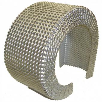
Embossing creates a controlled three-dimensional pattern in thin sheet. In heat-shield applications, the raised pattern can improve rigidity and help a thin metal sheet retain its shape after cutting and forming.
However, the embossed sheet is no longer identical to the original flat sheet. The pattern changes local geometry and introduces deformation before the final part is formed. For that reason, embossing depth, pattern and forming sequence should be considered together.
When specifying an embossed metal heat shield, define at least:
BSTFLEX supplies embossed stainless steel heat shield sheet in several thin-gauge options and supports different embossing patterns. An embossed aluminum heat shield sheet is also available for projects requiring an aluminum construction.
The material pages should remain the purchasing destination for raw or semi-finished sheet. A finished stamped shield should instead be specified by its final geometry, mounting and application requirements.
Not every surface benefits from embossing.
A mounting face may need to seat against a bracket. A washer may require a defined bearing area. A datum used during inspection may need a stable reference surface. A flange may need to mate with another part without an embossed peak changing its position.
These locations should be marked on the drawing as flat or otherwise controlled areas where necessary.
For example, a broad shield body may use an embossed pattern while the areas immediately around mounting holes remain flat. That does not make the flat zones less important. They may be the features that control how the entire shield sits on the vehicle.
Large unsupported sheet-metal areas can be flexible. A formed rib or bead can change local stiffness without simply increasing the base-metal thickness across the entire component.
For a heat shield drawing, identify which ribs are functional and which geometry may be adjusted during manufacturing review.
A functional rib may be used to:
Do not assume that copying the visual appearance of an existing rib automatically reproduces its function. The surrounding material, depth, direction and relationship to the mounting features all matter.
Likewise, adding extra ribs to make a part “stronger” is not automatically an improvement. The change may affect forming, clearance, weight, vibration response or the space available around the exhaust.
A flange is often one of the most important features in a formed metal heat shield. It can stiffen an edge, provide an attachment surface or define the interface with another component.
The RFQ should distinguish several flange-related requirements:
| Flange feature | What the buyer should define |
|---|---|
| Flange position | Its relationship to the main shield geometry and mounting reference |
| Flange angle | Nominal orientation and any fit-critical requirement |
| Flange width | Required bearing or structural area |
| Hole location | Position relative to the approved datum system |
| Adjacent clearance | Space required around exhaust, hoses, brackets or body components |
| Edge treatment | Cut, folded, rolled or otherwise specified finishing requirement |
If a flange is bent by hand during every trial installation to make the holes line up, the project does not yet have a controlled production geometry. The adjustment should be measured, reviewed and transferred into the approved design where appropriate.
Thin metal heat shields can have long exposed edges, including areas reached during vehicle assembly or maintenance. Edge geometry therefore affects more than appearance.
Depending on the project, an edge may be:
The appropriate option depends on the sheet thickness, part geometry, tooling and application. Do not specify a rolled or hemmed edge purely from a photograph without checking whether the material and surrounding geometry allow that operation.
Where an edge is likely to be handled during assembly, identify that requirement during the design review rather than after production tooling is complete.
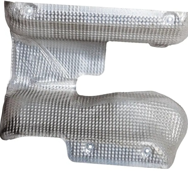
A mounting hole is only useful when its position is controlled relative to the rest of the shield.
For a custom stamped heat shield, define the reference system used to inspect critical mounting features. Avoid dimensioning every hole independently from unrelated outer edges if those edges do not control assembly.
The drawing should make clear:
Where the shield uses formed mounting tabs, the tab angle and the hole position should be evaluated together. A hole can meet its two-dimensional drawing coordinates and still be incorrectly positioned in the installed assembly if the tab has formed to the wrong angle.
Stamped exhaust shields frequently include openings for sensors, fittings, fasteners or service access.
A cut-out should therefore be dimensioned according to what it must clear rather than copied from an old sample without context.
When possible, identify:
A larger opening may simplify assembly while exposing more of the heat source. A smaller opening may improve coverage but make service impossible. The final geometry needs to balance both functions.
This distinction is important when comparing quotations.
A 0.20 mm metal sheet does not become a several-millimeter-thick metal sheet simply because the embossed pattern has greater overall profile height. Base-metal thickness and finished embossed profile are different dimensions.
For a multilayer shield, the distinction becomes even more important. The specification may need to identify:
Do not use one of these measurements as a substitute for the others.
A design can be easy to model in CAD and difficult to form repeatedly from thin sheet.
Tight radii, deep local shapes, abrupt transitions and multiple nearby features can place significant demands on the material during forming. An embossed sheet may behave differently from the same alloy in its original flat condition.
That is why the production supplier should review the proposed geometry before the buyer treats every feature as fixed.
The review should identify:
This does not mean the supplier should change the part without approval. It means manufacturability feedback should occur early enough that an approved change does not require an unnecessary redesign later.
The first sample should be checked against the drawing and the intended assembly.
For a stamped metal heat shield, useful sample checks include:
| Sample check | What to confirm |
|---|---|
| Overall fit | The shield matches the intended manifold, turbocharger or exhaust assembly |
| Mounting features | Holes, slots and tabs align without unexplained forcing |
| Clearance | Critical hot-side and protected-component distances remain acceptable |
| Embossing | Pattern and flat zones match the approved requirement |
| Formed ribs | Required ribs retain their intended location and geometry |
| Edges | Edge treatment matches the drawing and handling requirement |
| Service access | The shield does not obstruct required fasteners, sensors or maintenance points |
If the prototype requires trimming, bending or hole enlargement during installation, record the modification. The approved production drawing should describe the accepted geometry rather than relying on undocumented workshop adjustment.
BSTFLEX material pages and stamped-product pages serve different purchasing intentions.
The Stainless Steel Thermal Barrier Sheet and Embossed Aluminum Thermal Barrier Sheet are appropriate starting points when the buyer needs heat-shield material.
The Metal Stamping Heat Shields category is the correct route when the requirement is a finished formed component.
For an existing application, buyers can also review the Exhaust Manifold Heat Shield and Stamped Turbocharger Heat Shield as examples of rigid exhaust shielding.
A useful RFQ gives enough information to understand both the part and its installation.
Include:
Where a detail has not yet been finalized, identify it as open for manufacturing review instead of assigning an arbitrary value simply to complete the drawing.
Embossing creates a three-dimensional pattern in thin sheet that can increase rigidity and help the material maintain its shape. The embossing pattern must still be considered together with subsequent forming operations and the final shield geometry.
No. Sheet thickness describes the base metal. Embossed height describes the three-dimensional surface profile produced by the pattern. They should be specified separately.
Flat zones may be required around mounting holes, inspection datums, mating surfaces or other locations where an embossed surface would interfere with assembly or measurement.
Yes, a formed heat shield can incorporate ribs, beads, tabs, flanges, holes and other application-specific features. Their geometry and manufacturability should be reviewed as part of the complete part design.
A controlled drawing is preferred for defining production requirements, while a physical sample can provide useful geometry and installation context. For replacement development, identify any wear, distortion or previous modification on the sample before treating it as the production reference.
BSTFLEX supports custom metal heat shield projects based on drawings, samples and installation requirements. Material, thickness, embossing, geometry, mounting and validation requirements should be confirmed for the individual project before production.
BSTFLEX supports custom rigid exhaust shielding for automotive and industrial applications. Current metal heat-shield products include formed manifold and turbocharger shielding, while embossed stainless steel and aluminum materials are available separately for material purchasing requirements.
Send BSTFLEX your heat shield drawing, sample or installation information with the material requirement, critical mounting features, expected quantity and sample-approval requirements.

No.10, Chuangxin North Road, Nanshan Park, Ningguo Economic and Technological Development Zone, Ningguo City, Anhui Province, China
teléfono/Whatsapp : 0086-15856303740
Email : sales@bstbraidedsleeve.com
Skype : vanesa-cheng